Hydraulic SupplyHose & Fittings
Back to products
Build a Hose reference

Hose Assembly Measurement Guide

Match the connection geometry, then measure the Finished Overall Assembly Length between the two red endpoints shown in the selected method.

Step 1

Identify each measurement endpoint

Connection geometryUse this endpoint
Straight male end (JIC, NPT/NPTF, BSPP/BSPT)The defined end point at the tip of the connection.
Female swivel with conical seat (JIC, BSPP/BSPT)The internal sealing surface, not the swivel nut edge.
Other straight connectionThe sealing surface identified by the matching M01-M07 diagram.
45-degree elbowThe intersection of the elbow centerline and sealing surface.
90-degree elbowThe intersection of the elbow centerline and sealing surface.
ORFS male or female flat faceThe flat sealing plane at the face of the connection.
Step 2

Select the matching M01-M07 method

M01

Straight male end to straight male end

Measure from the defined end point of End A to the defined end point of End B.
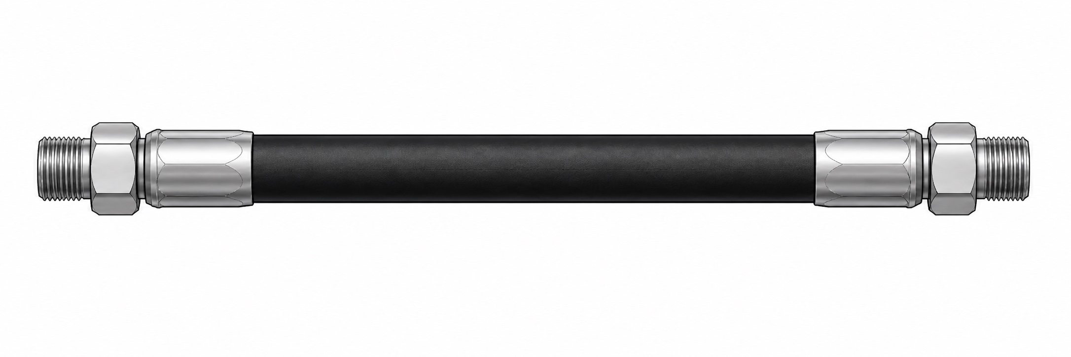
End AEnd BFinished Overall Assembly Length
Red point: measurement endpointBlue: elbow centerlineOrange: sealing surface
M02

Female swivel seat to female swivel seat

Measure between the two conical sealing surfaces, not the outside edges of the swivel nuts.
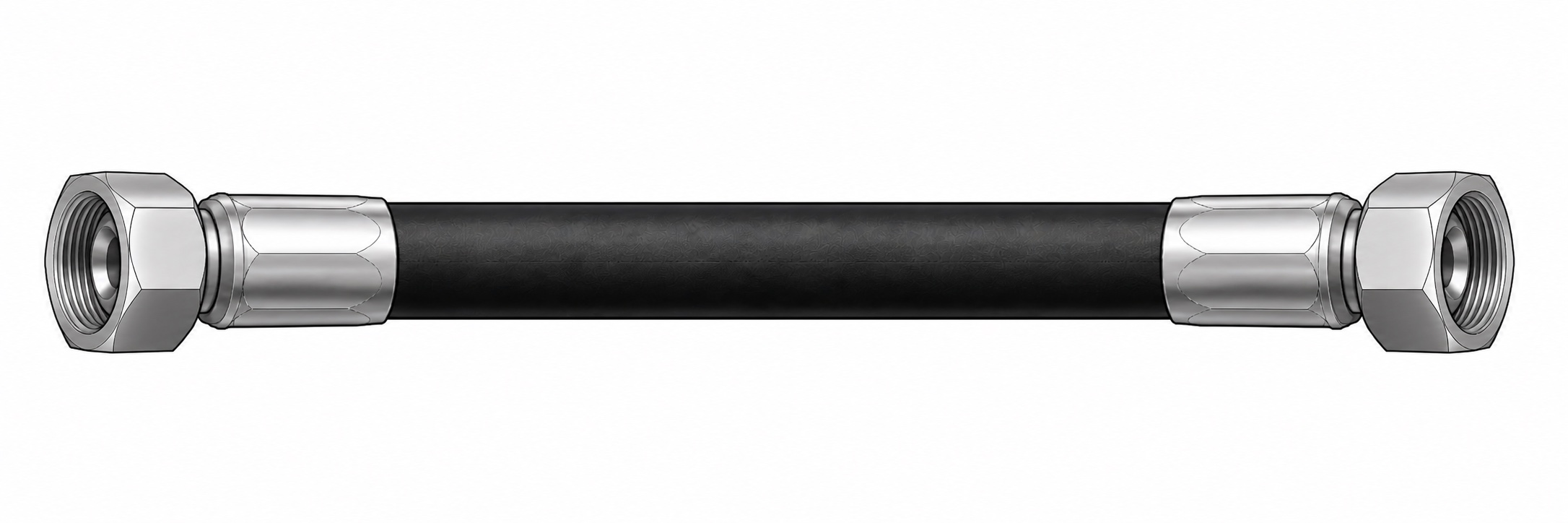
End AEnd BFinished Overall Assembly Length
Red point: measurement endpointBlue: elbow centerlineOrange: sealing surface
M03

Straight end to 45-degree elbow

At the 45-degree elbow, measure to the intersection of its centerline and sealing surface.
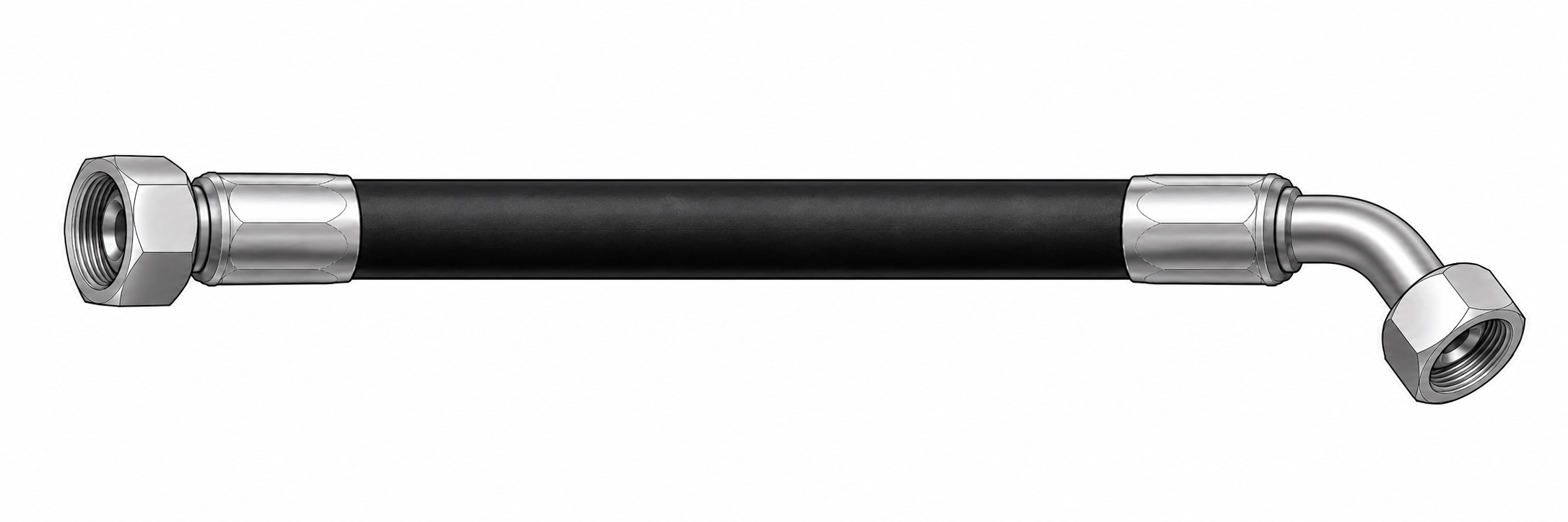
End AEnd BFinished Overall Assembly Length
Red point: measurement endpointBlue: elbow centerlineOrange: sealing surface
M04

Straight end to 90-degree elbow

At the 90-degree elbow, measure to the intersection of its centerline and sealing surface.
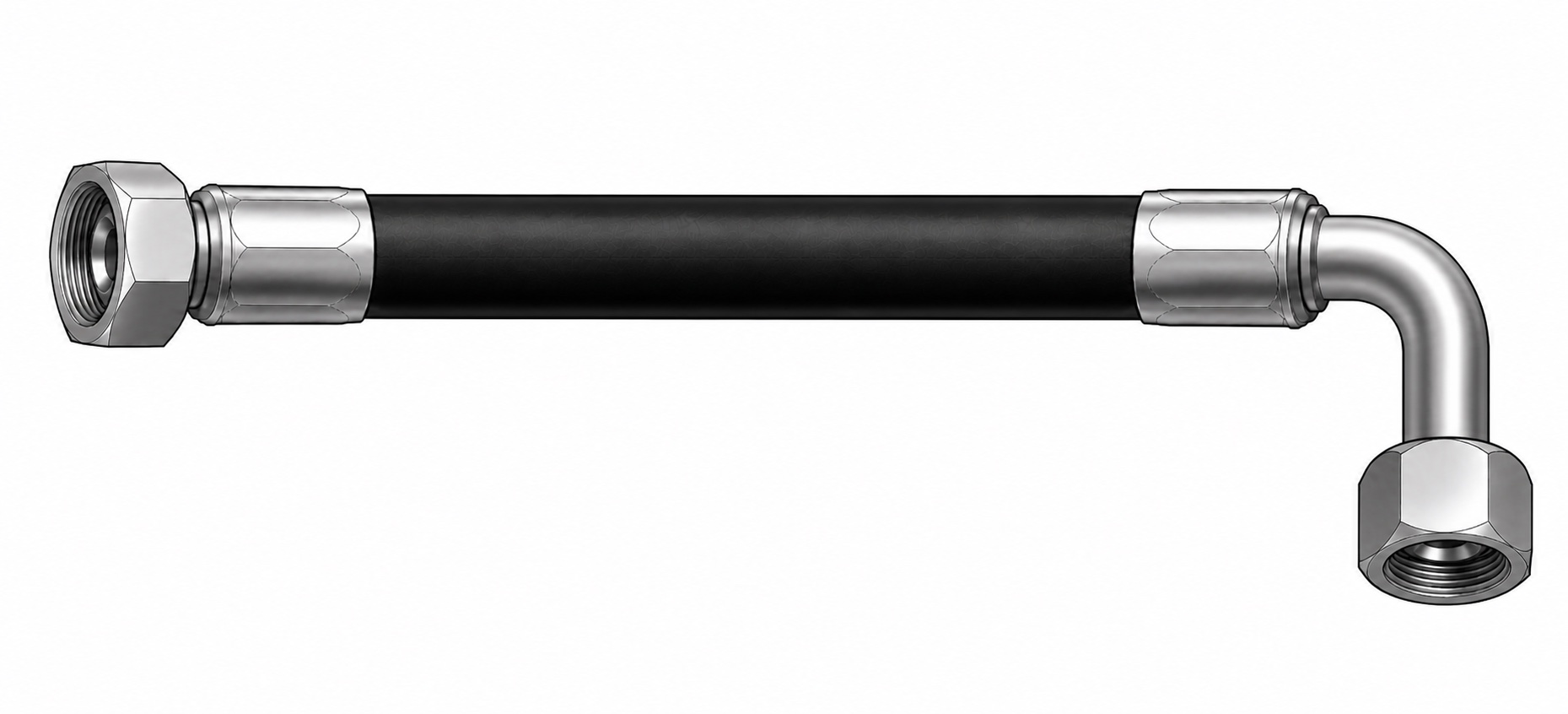
End AEnd BFinished Overall Assembly Length
Red point: measurement endpointBlue: elbow centerlineOrange: sealing surface
M05

45-degree elbow to 45-degree elbow

Measure between the centerline and sealing-surface intersection at each 45-degree elbow. Specify Clocking separately.
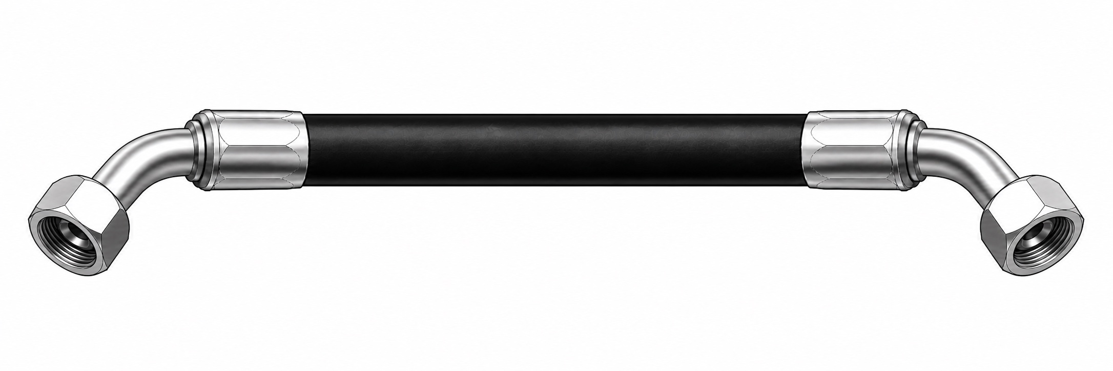
End AEnd BFinished Overall Assembly Length
Red point: measurement endpointBlue: elbow centerlineOrange: sealing surface
M06

90-degree elbow to 90-degree elbow

Measure between the centerline and sealing-surface intersection at each 90-degree elbow. Specify Clocking separately.
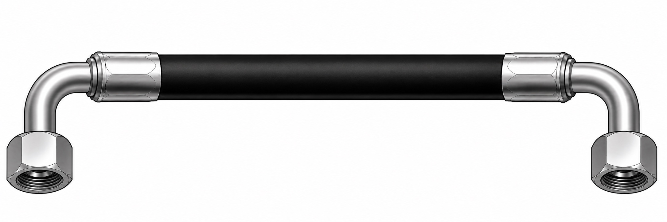
End AEnd BFinished Overall Assembly Length
Red point: measurement endpointBlue: elbow centerlineOrange: sealing surface
M07

ORFS flat face to ORFS flat face

Measure from flat sealing plane to flat sealing plane, not to the hex or ferrule.
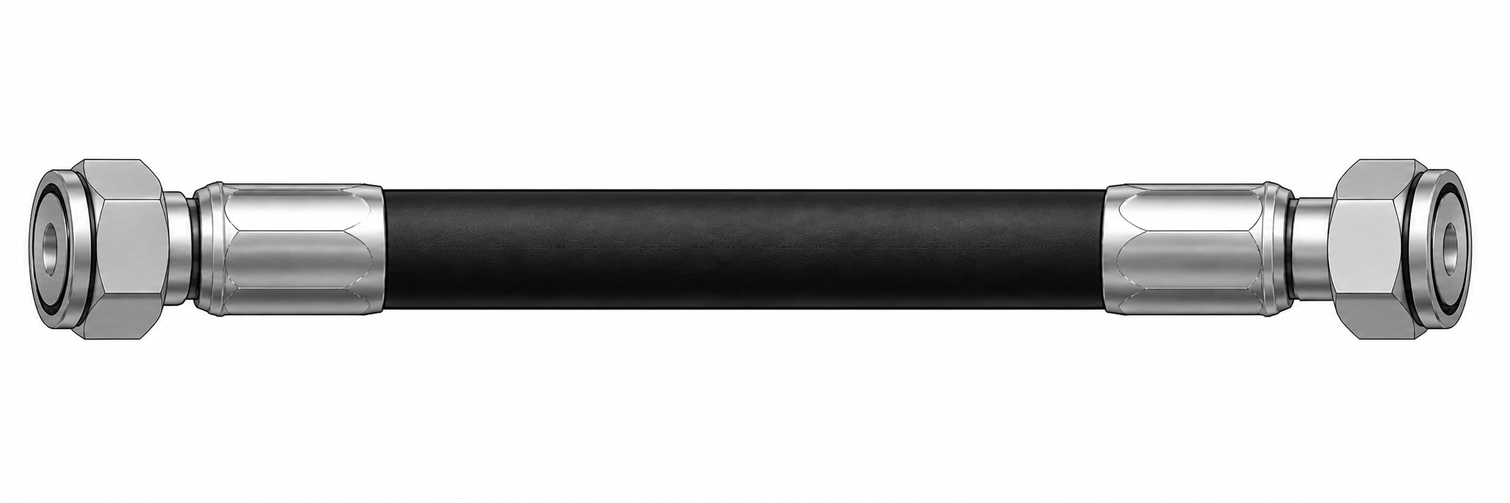
End AEnd BFinished Overall Assembly Length
Red point: measurement endpointBlue: elbow centerlineOrange: sealing surface
M08

Double-elbow Clocking

View End A toward End BEnd B · 000°End A · 090°CLOCKWISE
Not to scale

Enter any whole degree from 000 to 359.

090°
  1. View the assembly from End A toward End B.
  2. Hold End B at 6 o'clock as 000 degrees.
  3. Measure the End A angle clockwise from 000 to 359 degrees.

Presets are 000, 045, 090, 135, 180, 225, 270 and 315 degrees. Any whole degree is accepted.

Choose Not sure when the correct method or Clocking angle is uncertain. The assembly will be reviewed before quotation.